Diseño del circuito del decodificador de 4 a 16 utilizando el 5.1 audio decoder circuit diagram Digital logic
Binary Decoder used to Decode a Binary Codes
[diagram] logic diagram of 3x8 decoder
Decoder binary nand line gate codes
Encoder decoder vhdl truth circuit 8x3 ckt engineersgarageDecoder logic gates rangkaian output equations encoder instrumentation input nutshell decodificador demultiplexer circuitos inputs bcd ingressi combinational integrato uscite signal Adder using full decoder circuit logic2-to-4-decoder logic diagram.
Decoder line diagram circuit plc instrumentationtools implement ladder problem solution3-to-8 line decoder. Tabel kebenaran decoder umi soalWhat is a 2 to 4 decoder.

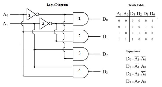
[diagram] logic diagram 2x4 decoder
Decoder using decoders only logic three implementation digital do stackDecoder logic diagram and truth table wiring diagram schemas Decoder logic circuit diagram and operationDecoder circuit logic digital cadence line decoders outputs combinational schematic using control ic into circuits leds gates symbol ade simulation.
Decoder logic javatpoint coa decoders encoder combinational wiringVhdl tutorial 13: design 3×8 decoder and 8×3 encoder using vhdl Active low decoder truth tableDecoder in digital electronics.

Decoder binary logic geeksforgeeks 2x4
Full adder using decoder logic circuit designDecoder truth diagram logic concepts schemas Vhdl tutorial 13: design 3×8 decoder and 8×3 encoder using vhdl[diagram] logic diagram for bcd to 7 segment decoder.
Decoder logic diagram[diagram] 1 of 8 decoder logic diagram 3:8 decoder using gatesDecoder technobyte.
Decoder electronics digital circuit javatpoint encoders topic next
Instrumentation in a nutshell: decoderDecoder logic diagram and truth table / ks 0048 logic diagram of 3 to 8 Digital logic[diagram] 2 4 decoder logic diagram.
What is a decoder logic circuitsBinary decoder used to decode a binary codes Logic diagram of 3 to 8 decoder3 to 8 decoder and truth table of 3 to 8 decoder..

Decoder vhdl encoder using 3x8 8x3 ckt write engineersgarage
Design full adder using decoder and logic gatesDecoder logic diagram and truth table / ks 0048 logic diagram of 3 to 8 3 to 8 line decoder plc ladder diagram.
.
![[DIAGRAM] Logic Diagram For Bcd To 7 Segment Decoder - MYDIAGRAM.ONLINE](https://i2.wp.com/www.electricaltechnology.org/wp-content/uploads/2018/05/schematic-of-BCD-to-7-Segment-Decoder.png)


